 POMPA
POMPAFire FightingPumps
End suction, double suction, in-line and multistage fire pumps within the scope of NFPA 20, feeding sprinkler, fire hose cabinet, hydrant and other water-based fire fighting systems.
4 pump types, one duty
Technical data for each type, the selection table based on NFPA 20 rated capacities and the applications are on the product page.
 01
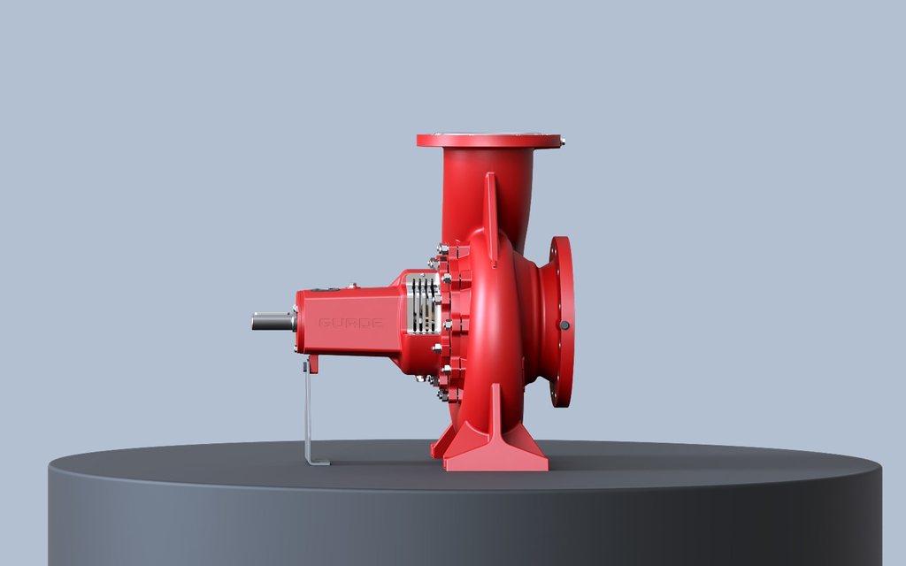
01End Suction Fire Pumps
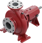
End suction fire pumps are horizontal, single-stage centrifugal pumps with volute casing and closed impeller.
- Capacity
- 25 – 5000 GPM
- Head
- 40 – 100 m
- Discharge flange
- DN32 – DN250
- Casing pressure
- 10 – 16 bar
 02
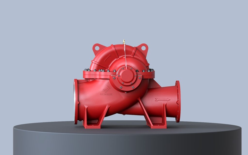
02Double Suction Fire Pumps
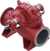
Double suction fire pumps have a wide capacity and head range, and allow easy maintenance and repair without dismantling the motor and pipework.
- Capacity
- 400 – 5000 GPM
- Head
- 50 – 140 m
- Discharge flange
- DN65 – DN200
- Casing pressure
- 16 – 25 bar
 03
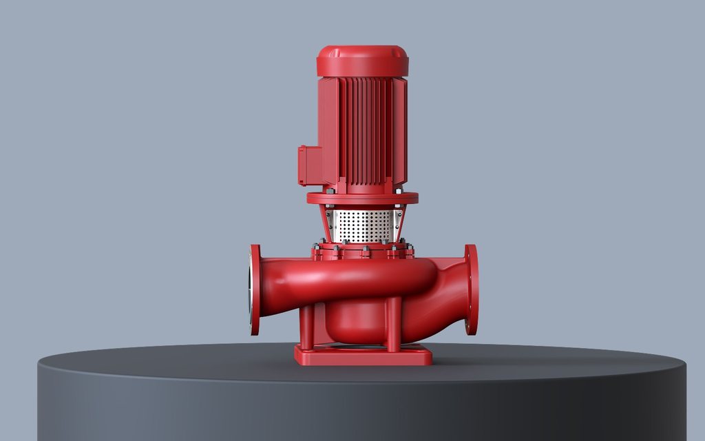
03In-Line Fire Pumps
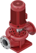
In-line fire pumps are single-stage, close-coupled centrifugal pumps with volute casing and closed impeller that can be connected to straight pipework.
- Capacity
- 25 – 1250 GPM
- Head
- 30 – 90 m
- Discharge flange
- DN40 – DN200
- Casing pressure
- 10 – 16 bar
 04
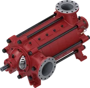
04Horizontal Multistage Fire Pumps
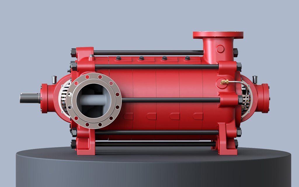
Horizontal multistage fire pumps are radially split casing, end suction, multistage centrifugal pumps with closed or semi-open impellers.
- Capacity
- 25 – 2500 GPM
- Head
- 60 – 170 m
- Discharge flange
- DN32 – DN200
- Casing pressure
- 30 bar
Which pump, which motor?
Select the rated capacity and head; the corresponding pump size and motor power are listed for the four types.
Rated capacity (GPM)
Head (m)

NFPA 20 fire fighting pumps
NFPA 20 – STANDARD FOR THE INSTALLATION OF STATIONARY PUMPS FOR FIRE PROTECTION
NFPA 20 is the globally recognised basic standard for the selection and installation of stationary fire pumps. This standard aims to ensure that pumps supplying water to sprinkler systems, fire hose cabinets, hydrant systems and other water-based fire fighting systems are correctly selected, safely installed and reliably deliver the expected capacity and pressure in the event of a fire. It covers stationary pumps used for fire protection, including horizontal and vertical centrifugal pumps, vertical turbine pumps and positive displacement pumps.
Performance characteristic · representative curve
Rated capacities (GPM)
According to NFPA 20, the rated capacities of fire pumps cannot differ from these values.
System features
- Starts automatically in the event of fire
- Meets the specified nominal capacity and pressure values
- Standby, monitoring and control functions are defined
- Acceptance tests and periodic inspections are specified
Performance criteria
- At closed valve (zero flow), head is no more than 140% of the rated value
- The head at 150% capacity cannot be less than 65% of the rated value
- At rated capacity, the flow velocity in the suction pipe is less than 3 m/s
UL Listed / FM Approved
UL LISTED / FM APPROVED FIRE FIGHTING PUMPS
The UL Listed and FM Approved marks indicate that fire pumps have been tested and certified by independent international organisations in accordance with the relevant standards. In this way, the investor and the operator safeguard their facility with a certified, globally recognised protection system that has been tested to come into operation in the event of fire.
UL / FM test criteria
- Meeting the specified capacity – pressure curve
- Continuous operation and durability
- Reliable start-up and continuity of performance
Advantages
- Easy acceptance and credibility with insurance companies and regulatory bodies
- Documented performance supporting system design in compliance with NFPA 20
- International-standard safety in high-risk facilities (industrial plants, power plants, large warehouses, shopping centres, etc.)
Design features in accordance with UL / FM
- The declared capacity may only be one of the standard rated capacities; above 5000 GPM it increases in 500 GPM steps
- All bolts, screws, etc. in contact with the pumped liquid are of bronze or corrosion-resistant material
- Supplied together with automatic air release valve, casing relief valve and pressure gauges
- Bearings with an L-10 life of at least 5000 hours at maximum load
- At least 4 rings of soft packing and a lantern ring (at least 5 rings if there is no lantern ring)
- Impeller, wear rings, shaft, lantern ring and glands made of corrosion-resistant material
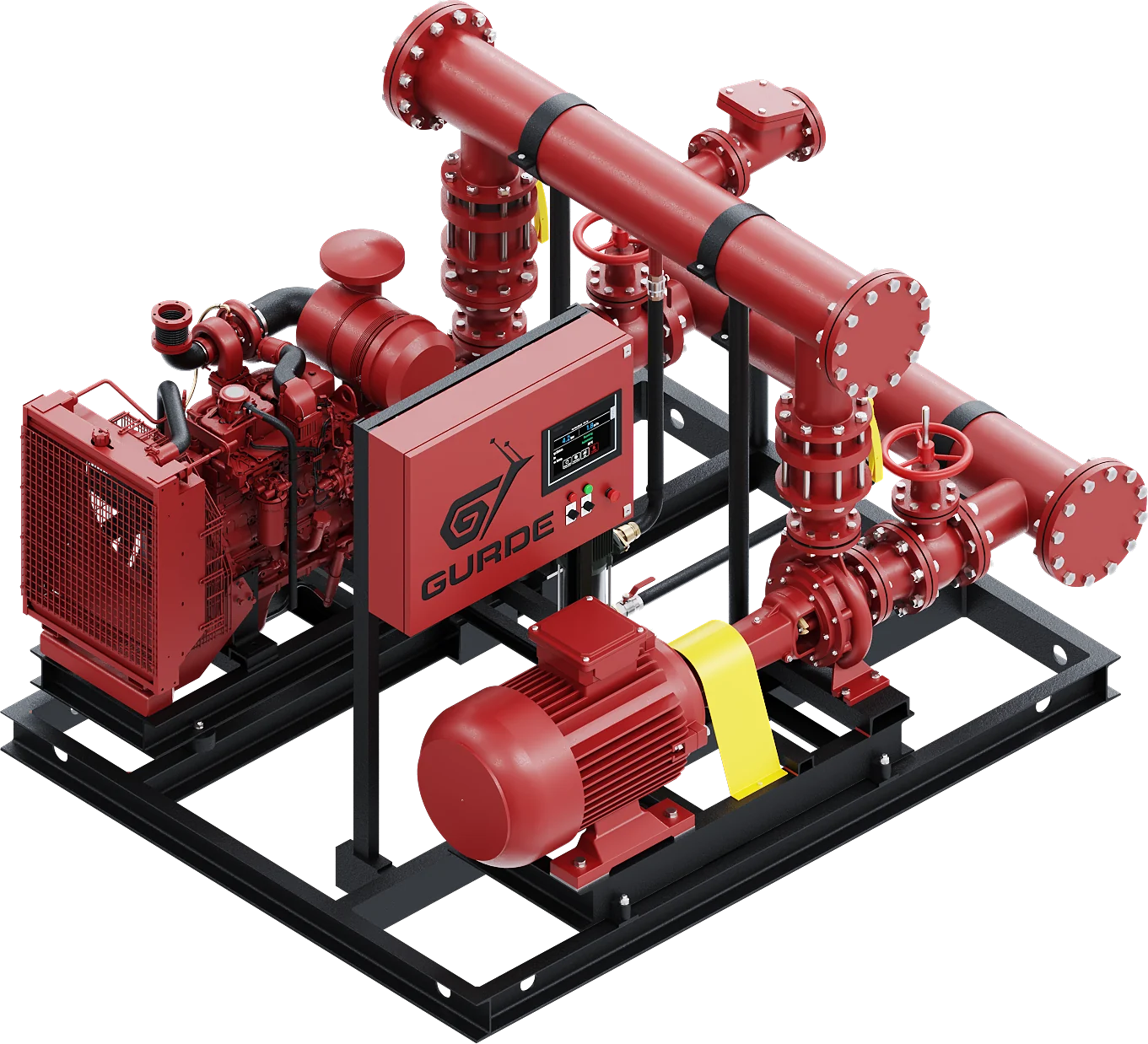
Fire pump set: complete packaged system
Main pump, standby pump, jockey pump, control panels, manifolds and valves on a common base frame; ready to be tested as a system.
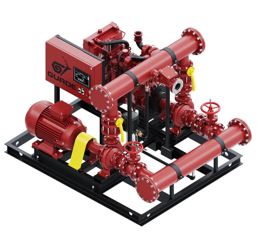
The fire pump set is a complete packaged system comprising the main pump, standby pump, jockey pump, panels, manifolds, valves, etc., all on a common base frame. If one pump is used in the system, a standby pump of the same capacity is required.
Start-up sequence
When the system pressure falls below the set value, the jockey pump starts first on a signal from the pressure switch. If the pressure continues to fall, the main pump starts; if the system pressure still cannot be maintained, the standby pump starts.
If automatic stop is required, once the pressure has returned to normal the electric motor-driven pump is stopped after running for at least 10 minutes, and the diesel engine-driven pump after running for at least 30 minutes.
PSYSTEMNormal · system at pressure, pumps in automatic modePJSETPressure maintenance (jockey) pump startsP1SETMain pump (electric motor driven) startsP2SETStandby pump (diesel engine driven) starts upSetting sequence: PSYSTEM > PJSET > P1SET > P2SET
All types, in a single table
| Pump type | Suction flange | Discharge flange | Capacity | Head | Speed | Operating temperature | Casing pressure |
|---|---|---|---|---|---|---|---|
| 01End Suction Fire Pumps | DN50 – DN300 | DN32 – DN250 | 25 – 5000 GPM | 40 – 100 m | up to 3000 rpm | -10 °C to +120 °C | 10 – 16 bar |
| 02Double Suction Fire Pumps | DN100 – DN250 | DN65 – DN200 | 400 – 5000 GPM | 50 – 140 m | up to 3000 rpm | -20 °C to +80 °C | 16 – 25 bar |
| 03In-Line Fire Pumps | DN40 – DN200 | DN40 – DN200 | 25 – 1250 GPM | 30 – 90 m | up to 3000 rpm | -10 °C to +110 °C | 10 – 16 bar |
| 04Horizontal Multistage Fire Pumps | DN40 – DN250 | DN32 – DN200 | 25 – 2500 GPM | 60 – 170 m | up to 3000 rpm | -10 °C to +140 °C | 30 bar |
